
Abrasive Testing Field Trials on Diverse Substrates
Every shop has that one job that rewrites the rulebook. Mine was a mixed-material retrofit in an old boathouse: aluminum frames, oak trims, polycarbonate glazing, and a painted steel hoist beam all begging for different forms of persuasion. Time was short, humidity high, and the client wanted a uniform finish before a single new coating was opened. On paper, the abrasive sequence looked standard; on the floor, it unraveled fast. The film-backed discs that loved oak burned the aluminum; the garnet that carved the paint off steel barely scuffed the polycarbonate; the anti-loading stearates that helped the resin stay clean on wood smeared under heat on plastic. That day re-taught me an old lesson: controlled abrasive testing is not a lab luxury—it’s the difference between rework and repeatability, especially when you’re negotiating substrates that change hardness, toughness, and thermal response every few meters.
Field trials thrive on this chaos. They acknowledge that a random-orbit sander on a humid morning is a different animal than a belt machine in a climate-controlled bay. They respect that concrete dust will clog a closed-coat 80-grit ceramic faster than you can swap pads, and that aluminum can gall to a zirconia belt if your contact pressure drifts by even half a kilogram. Most of all, they give you data that calibrates instincts: cut rate you can chart, loading you can predict, scratch pattern you can reproduce. When you’re tasked with surface preparation on diverse substrates, the smartest move is not guessing the “universal” abrasive—it’s building a workflow that measures how each candidate cuts, clogs, and wears in your real environment. That’s where disciplined abrasive testing pays out in faster throughput, longer media life, and coatings that adhere the first time.
Quick Summary: Field-focused abrasive testing across metals, plastics, woods, and concrete turns guesswork into repeatable surface prep by quantifying cut rate, loading, temperature, and finish.
Why field trials outperform lab assumptions
Lab data is a good starting point, but it often ignores the stacked variables of real jobs: fluctuating humidity, operator technique drift, equipment wear, and substrate variability within the same project. In a lab, silicon carbide film may show exceptional scratch uniformity on PMMA; on site, airborne dust turns that same film into a clogged disc in minutes. Similarly, grit fracture behavior depends on true contact pressure and angle—both tough to keep constant when you’re on a ladder or inside a tank shell.
A robust field trial addresses four practical gaps:
Substrate heterogeneity. Aluminum extrusions may carry mill anodize traces or oxide blooms; hardwoods vary by growth ring density; concrete varies by aggregate exposure. These differences change chip formation and heat generation.
Energy coupling. The effective energy delivered to the abrasive depends on backing compliance, pad wear, and even hose pressure in pneumatic tools. Field trials let you measure under your exact tool stack.
Process constraints. You might need low dust, low heat, or minimal edge rounding. Lab rigs don’t reflect those production constraints, but field trials can.
Continuous finish readiness. Surface prep is judged by what happens next—adhesion, gloss, or sealant wetting—so trial metrics should tie to downstream results, not just isolated roughness numbers.
Design your trial to mimic the real run. That means setting a fixed traverse speed on a belt sander using a marked jig, logging actual tool RPM under load, and weighing both the workpiece and the abrasive before and after. Record ambient temperature and relative humidity. If possible, log surface temperatures using an IR thermometer after fixed intervals. These operational measurements will reveal which media type—alumina, zirconia, ceramic microfracturing alumina, or silicon carbide—delivers stable cut rate without excess heat or loading. On-site evidence will usually contradict at least one lab assumption; embrace that learning curve and bake it into your standard operating procedures.
Designing abrasive testing for real substrates
An effective field protocol starts with a clear objective—material removal, profile, or cosmetic clarity—and a small design of experiments (DOE) that isolates variables you can control. With diverse substrates, build a matrix that covers at least four material families: ferrous metals (e.g., blasted steel or painted mild steel), nonferrous metals (e.g., aluminum 6061-T6), plastics (e.g., PC and PMMA), and porous/mineral (e.g., fiber-cement or cured concrete). For each material, define your target endpoint: a 60–80 µm anchor profile for coating on steel, a haze-free 3–5 µm Ra for PMMA, or a laitance-free CSP-3 for concrete repair.
Key factors to set and track:
Abrasive type and structure: aluminum oxide vs. zirconia vs. ceramic; closed-coat vs. open-coat; stearate loading; coated abrasive backing (film vs. C-weight paper vs. Y-weight cloth); for blasting, media morphology (angular vs. spherical) and size.
Process mechanics: normal force (kg), tool speed (RPM or m/s belt speed), pass count or dwell time, contact angle, and pad/compliance type.
Environment: temperature, RH, dust extraction CFM, vacuum pad hole alignment.
Measurement plan: cut rate (g/min or µm/pass), media wear (mass loss or visual grit retention), loading index (image-based pore occlusion), surface temperature rise (ΔT), and finish metrics (Ra/Rz or optical haze).
Actionable tips to keep trials lean and conclusive:
- Normalize force with a spring-scale handle or inline load cell; do not rely on “feel.”
- Mark traverse lanes and time each pass to nail down contact time consistency.
- For plastics, cap surface temperature at 45–50°C using IR checks to prevent thermal smearing; switch to film-backed SiC with light stearate when approaching finishing grits.
- On aluminum, bias toward ceramic alumina or zirconia with open-coat to cut galling; run fresh pads at higher speed with lighter force to reduce adhesive wear.
- For concrete, pre-vacuum and dampen slightly for wet sanding to minimize dust loading; select lower-closed coat grits or diamonds depending on CSP target.
Capture data in a single sheet per substrate with photos, mass deltas, and roughness/haze readings. When the trial ends, you should be able to select a grit sequence (e.g., 80C ceramic → 120A alumina → 220 SiC film) tied to explicit force, speed, and environmental windows—not tribal memory.
Surface preparation variables you can control
Field outcomes hinge on a handful of variables that operators can standardize. Force, speed, contact compliance, and dust extraction govern cut rate and scratch integrity far more than brand labels do.
Force. Too little pressure skates the abrasive and polishes peaks; too much fractures grains prematurely, increases heat, and risks deep striations. On 150 mm random-orbit sanders, 3–5 kg applied force is a common sweet spot for wood and plastics, while metals may favor 5–7 kg for stock removal. Use a bathroom scale on a benchtop to coach the team toward the right load.
Speed. Belt speed and pad RPM influence chip thickness and heat. For aluminum and acrylics, higher speed with lighter pressure promotes sliding chips and reduces galling or smearing. For steel paint removal, moderate speed with firm pressure stabilizes cut rate without overheating.
Compliance. Backup pad durometer and platen stiffness impact scratch depth and edge roll-off. A soft interface pad evens out sanding on contoured oak but risks rounding edges on steel brackets. Keep a documented pairing: e.g., medium pad for 80–120 grit on metal, soft pad only at ≥220 grit on wood.
Extraction. Dust extraction keeps pores open, delaying loading and preserving cutting points. Verify pad hole alignment and vacuum CFM; misaligned holes can cut cut-rate by 20–30% within minutes. For concrete, a HEPA extractor with auto-pulse cleans filters and keeps CSP uniform.
Cooling and lubrication. Wet sanding on plastics and concrete can stabilize temperature and reduce micro-tearing, but it changes debris transport. If you choose wet, switch to waterproof backings and note that Ra drops differently; recalibrate your end-point visual checks.
H3: Substrate-specific adjustments
Steel and ferrous alloys: When blasting, align media per EN ISO 11125-5 principles—control shape (grit vs. shot), size distribution, and hardness to target an anchor profile without over-peening. In coated abrasives, ceramic microfracturing grains maintain sharpness at higher loads; watch for heat tinting near thin edges.
Aluminum and copper alloys: Fight loading with open-coat zirconia or ceramic and aggressive extraction. Keep a strict ΔT limit; once oxide smearing starts, reduce force, switch to a sharper mineral (SiC), or move to wet.
PC/PMMA: Prevent scratch haze by moving to film-backed SiC at finishing stages. Work in cross-hatched passes and verify haze numerically if possible; aim for low Ra coupled with no directional scratch under raking light.
Hardwood and veneers: Start coarser than you think (80 or 100 ceramic) to flatten, then climb grits in 1.6–2.2× steps (e.g., 100 → 150 → 220). Lock grain-raising with a controlled water wipe before final grit to avoid post-finish telegraphing.
Interpreting cut rate, wear, and finish
Collecting numbers is half the battle; knowing what they mean keeps you from chasing noise. Start with the trio: material removal rate (MRR), abrasive wear, and finish quality.
MRR. For flat panels, weigh the panel before and after a fixed pass count. For metals, track g/min; for plastics and woods, µm/pass via depth markers or mass plus density. A stable MRR across passes signals durable grains and controlled loading; a steep falloff indicates clogging or excessive grain fracture.
Abrasive wear. Weigh discs or belts, or rate visually with a standardized 0–5 retention scale using macro photos. Distinguish bond failure (grain shedding) from dulling (rounded facets). Ceramic alumina should show microfracture with maintained sharpness; if you see shelling, you’re over-pressured or overheating.
Finish metrics. Roughness (Ra/Rz), profile (for coatings), and haze/gloss tell different stories. Metals prepped for high-build coatings may accept higher Ra if peak density supports adhesion. Plastics and varnish-ready hardwoods care about scratch pattern uniformity as much as absolute Ra.
Statistically, run at least three replicates per condition to calculate coefficient of variation (CV). A CV under 10% for MRR and under 15% for finish is a practical field target. Use control charts for longer jobs to detect drift—belt glazing, pad wear, or extraction loss.
Tie measurements to downstream performance. Adhesion pull tests on coated panels or tape tests on primers will validate whether your profile and cleanliness were sufficient. On plastics, solvent wipe tests post-sanding can reveal stress crazing risk; if crazing appears, step back to finer grit or reduce heat.
According to a article, different scratch and abrasion methods can rank the same coating differently depending on substrate and thickness—mirroring what we see in field variability. Use that insight to avoid over-trusting a single metric. Align your field indicators with the failure modes you most want to prevent: delamination on steel, haze on PMMA, or edge-rounding on thin veneers.
Finally, visualize your result window. Define green/yellow/red bands for MRR, ΔT, and finish metrics per substrate. Your crew can then make fast, data-based calls—swap media, change force, or add extraction—without waiting for post-mortem analysis.
From trials to standard operating workflow
Turning trial lessons into standard work cements the gains. An SOP should translate measurement-heavy experiments into step-by-step procedures operators can execute consistently across shifts and sites.
Structure your SOP per substrate category:
Scope and endpoint. Specify the finish or profile target (e.g., CSP-3–4 on spalled concrete, Ra ≤ 0.6 µm for aluminum prior to chromate-free primer, haze-free PMMA panel).
Tooling stack. Lock in sander model, backup pad durometer, hose diameter/length, and extraction CFM. For belts, define platen type and belt speed.
Sequence. List abrasives by mineral, grit, coat type, and backing. Example (steel repaint): 80-grit ceramic closed-coat on Y-weight → 120-grit alumina closed-coat → brush and vacuum → solvent wipe as appropriate to specification.
Parameters. Document applied force range, pass count, traverse speed, and maximum allowable surface temperature. Include checkpoints: IR temperature after pass 2; loading check after pass 3; pad change when MRR drops >25%.
Quality gates. Define quick tests: Ra measurement with a portable profilometer for metals, cross-hatch tape test after primer flash, gloss/haze reading for plastics. For concrete, use replica tape or profile comparator plates.
Safety and cleanliness. Note PPE, dust class, and anti-static handling for plastics. For metals and concrete, specify when to use wet processes to control silica or aluminum dust.
Embed feedback loops. If the operator flags yellow-band conditions (e.g., rising ΔT, falling MRR), empower them with pre-approved adjustments—reduce force by 1 kg, swap to open-coat, or move to wet—before escalating. Include a brief defect catalog with remediation steps: galling on aluminum, swirl marks on oak under raking light, or insufficient anchor pattern on steel.
Train with real specimens. Keep a set of small panels—steel with old alkyd, anodized aluminum, PMMA offcuts, concrete coupons—to rehearse the sequence quarterly. Rotate operators through a timed, measured drill. Calibration sessions expose drift early: a tired backup pad, a vacuum fitting that slipped, or a new batch of belts with slightly different bond hardness.
With these practices, abrasive performance becomes predictable—and predictability is what lets you promise schedules and deliver finishes that pass inspection without surprises.
IKM Testing – — Video Guide
IKM Testing’s demonstration of multi-string conductor cutting with abrasive water jet technology showcases how controlled media, pressure, and delivery transform tough field cuts into precise separations. The clip highlights parameter selection—abrasive feed, jet focus, and traverse rate—and illustrates how process control translates to clean cuts on complex downhole assemblies.
Video source: IKM Testing – Cutting of Multi-String Conductors – Abrasive Water Jet Cutting
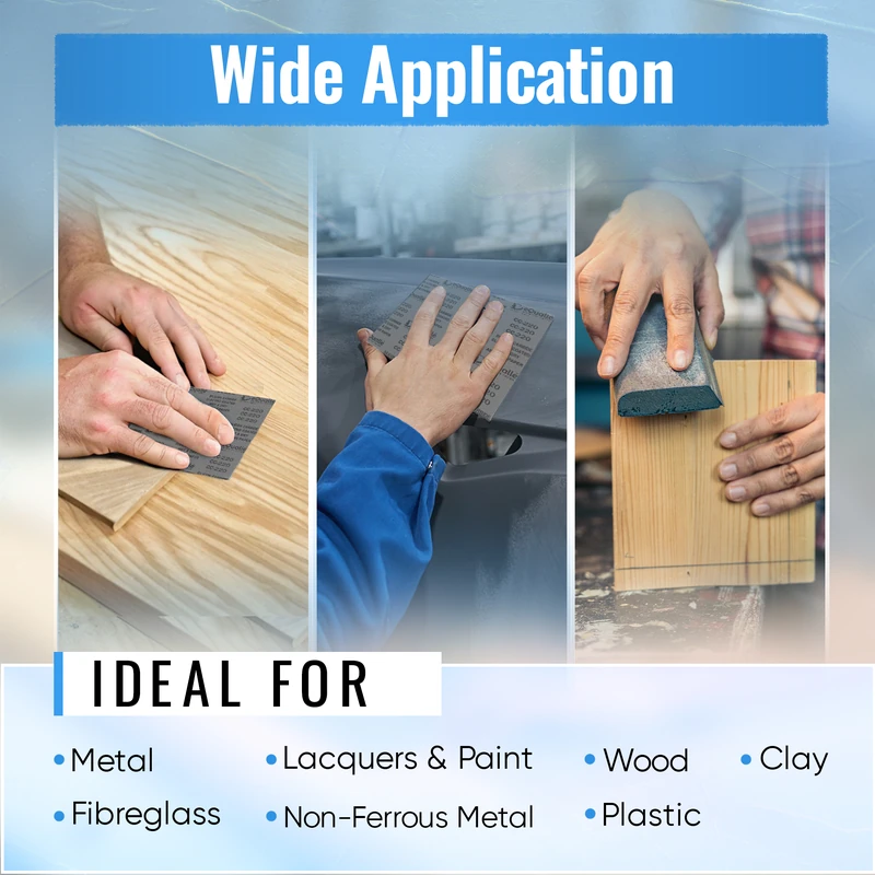
100 Grit Sandpaper Sheets (50-pack) — 9x11 in Silicon Carbide Abrasive for Wet or Dry Use — General-purpose coarse sandpaper for smoothing rough surfaces and removing old coatings. Works well on wood, metal, and resin projects. Designed for wet or dry sanding between aggressive 80 grit and finer 150 grit stages. (Professional Grade).
Frequently Asked Questions (FAQ)
Q: How many substrates should I include in a first-round field trial?
A: Start with four representative categories: a ferrous metal, a nonferrous metal, a clear or glossy plastic, and a mineral-based material like concrete. Two samples per category with three replicates per condition give you enough statistical confidence to pick winners without stalling production.
Q: What’s the fastest way to detect abrasive loading before performance collapses?
A: Track a simple loading index: weigh the disc before and after two timed passes and inspect pore occlusion under consistent photos. A 10–15% mass gain from debris or visible occlusion across 30–40% of the surface predicts imminent cut-rate drop; swap or clean the pad before MRR declines by 25%.
Q: Which abrasive minerals map best to which substrates?
A: As a rule: ceramic alumina for steel and heavy paint removal, zirconia alumina for aluminum and tougher alloys when loading is under control, silicon carbide for plastics and finishing passes due to sharper micro-cutting, and diamond or silica-carbide segments for concrete when targeting specific CSP levels. Adjust coat density and backing based on heat and contour.
Q: How do I connect roughness numbers to coating adhesion in the field?
A: Use roughness as a proxy but validate with adhesion tests. For metals, target Ra and peak density suitable for your primer, then confirm with cross-hatch or pull-off tests on witness panels prepped alongside the job. Document the combo of Ra, cleanliness, and adhesion; that trio becomes your acceptance criterion for future work.
Q: Can I generalize lab scratch or Taber abrasion results to my site?
A: Treat them as directional. Lab tests rank materials and media under controlled conditions, but field variables—humidity, operator force, dust extraction—shift outcomes. Use lab data to shortlist candidates, then run concise field trials to confirm cut rate, temperature behavior, and finish under your exact constraints.